START
Using
This Quick Start Manual
Use this Quick Start Manual to set up your Strain Gage Meter and begin
operation. Information is provided on how to:
ò Connect AC power
ò Connect the sensor
ò Set basic options for operation
ò Scale the meter.
For complete information on all setup options, please refer to the Strain
Gage Meter Operator's Guide.
NOTE: This Quick
Start Manual includes specific configuration parameters for bridge sensors
with an output range of 0û100 mV and 10 V excitation. Other sensor types
may require different parameters or additional ones. When this is the
case, we refer you
Before
You Begin
In addition to the meter and the related parts, you will need the following
items to set up your unit:
ò
110 Vac power
ò Sensor
ò 1/8-inch flat-blade screwdriver.
Mount
the Unit
1.
Cut a panel opening using the dimensions shown below.
2.
Position the unit in the opening, making sure the front bezel
is flush with the panel.
3. Install retaining clips on both sides of the meter and
tighten against the panel. |
|
Connect
AC Power
1.
Remove the panel at the back of the unit.
2. Locate the TB1 connector.
3. Insert the correct wire in each terminal as shown in the
figure above and tighten the lockdown screws.
4. Tug gently on the wires to verify the connections. |
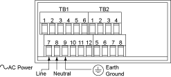
Main AC Power Connections
|
Connect
the Sensor
1.
Locate the TB2 connector on the rear of the unit.
2. Attach the sensor wires and tighten the lockdown screws.
The diagram below shows the wiring for bridge sensors with internal
excitation. Refer to the Operator's Manual for setup requirements
for other sensor types.
3. Tug gently on the wires to verify the connections.
4. Replace the panel at the back of the unit. |
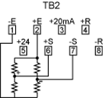
Bridge
Sensor with Internal Excitation
|
Turn
On the Unit
1. Apply ac power.
As the unit initializes, RST flashes on the front panel, and then a numeric
reading is displayed.
2. Verify that a numeric reading is displayed. If not:
ò Remove ac power
ò Verify the TB1 power connections
ò Check your power source
ò Apply ac power again.
Using
the Configuration Menu
To configure the meter, you use the buttons on the front panel.
|
To:
|
Take
This Action:
|
| Display
the Press the MENU button. |
The first function Configuration Menu on the menu, INPT, displays.
|
| Select
a submenu function |
1. Press MENU until the function you function want
is shown.
2. Press  /TARE. /TARE.
The information you can change flashes. |
| Select
a value for that that submenu function |
1. Press  /NT/GRS
to display the option you want. /NT/GRS
to display the option you want.
2. Press MENU to store it.
"STRD" quickly flashes, indicating that the selection has
been stored in memory. Then the next menu function displays. |
| Go
back to the previous menu function |
Press
RESET once. |
| Exit
the Configuration
Menu |
ò Press RESET twice. The unit displays "RST" as it
reinitializes. When a numeric value displays, the unit is in the
run mode.
ò Optionally, you can press MENU to move through all the
menu functions until the unit reinitializes. |
To
Set the Input Type
1.
Press MENU until the unit displays:
2. Press  /TARE.
The unit displays: /TARE.
The unit displays:
3. For this application you want 100M.
If 100M.is not displayed, press  /NT/GRS
until it appears. Other choices are 50 m, 10 V, 5 V, 0û20. Refer
to the Operator's Manual for more information on changing ranges. /NT/GRS
until it appears. Other choices are 50 m, 10 V, 5 V, 0û20. Refer
to the Operator's Manual for more information on changing ranges.
|
|
|
|
|
4. Press MENU to select the sensor shown. The meter
displays the next menu item. If you changed input type, the meter
displays:
|
|
|
|
To
Set the Decimal Point
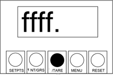
1. If it's not
already shown, press MENU until the unit displays:
2. Press
 /TARE.The unit
displays: /TARE.The unit
displays:
|
|
|
3. Press  /NT/GRS
to move the decimal point to the desired location. The factory setting
is FFFF. The other choices are FFF.F, FF.FF, and F.FFF. /NT/GRS
to move the decimal point to the desired location. The factory setting
is FFFF. The other choices are FFF.F, FF.FF, and F.FFF. |
|
4. Press MENU to select the decimal point position shown.
The unit displays: |
To
Scale the Meter
You can scale the meter in one of two ways:
1. With a known load ù This method uses input (load) information
sent from another device such as a scale or a simulator for voltage or
current.
2. Without a known load ù This involves calculating the load based
on transducer specifications and manually entering it to the meter.
For
both methods, you must first identify the minimum input load (IN1) and
the corresponding display reading you want (RD1). Then you identify the
maximum input load (IN2) and its corresponding display reading (RD2).
NOTE: The decimal
point is for display purposes only ù you set it where you want it to display
for your application. When entering IN1 and IN2 values, ignore any decimal
point on the display. However, you must enter RD1 and RD2 vaules with
the decimal point in the desired position.
Scaling With Known Loads
To identify the minimum known load (IN1 and RD1):
1. If it's not already shown, press MENU until the unit
displays:
2. Apply
the minimum known load (0%).
3. Press  /TARE
The unit displays:
Scaling
Without Known Loads /TARE
The unit displays:
Scaling
Without Known Loads
For 0û100 mV sensors, the values for the minimum and maximum input loads
are always as follows:
ò Minimum load (IN1) ù 0
ò Maximum load (IN2) ù 9999.
If your installation uses a different sensor type, you must calculate
the values for IN1 and IN2 before proceeding with the steps
below. Use the formula provided in the Operator's Manual.
To define the minimum load (IN1 and RD1):
1.
If it's not already shown, press MENU until the unit displays:(example
on left)
2. Press  /TARE.
The unit displays: /TARE.
The unit displays:
|
|

|
3. Press  /TARE.
again. The unit displays the last setting for IN1. (The first
digit flashes.) /TARE.
again. The unit displays the last setting for IN1. (The first
digit flashes.)
4.
Change IN1 as necessary:
ò Press  /NT/GRS
to set or change the digit's current value. Continue to press /NT/GRS
to set or change the digit's current value. Continue to press
 /NT/GRS
until the meter displays the desired value for the flashing
digit. Values can range from 0 to 9. For the first digit,
you can also enter a minus sign (û) or û1. /NT/GRS
until the meter displays the desired value for the flashing
digit. Values can range from 0 to 9. For the first digit,
you can also enter a minus sign (û) or û1.
ò Press  /TARE.
to scroll to the remaining digit(s) you want to change. /TARE.
to scroll to the remaining digit(s) you want to change.
|
|
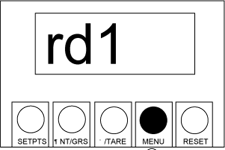
5. Press
MENU to store IN1. The unit displays: (example on left)
6. Press  /TARE. /TARE.
The unit displays the last setting for RD1. (The first digit flashes.)
|
|

|
7. Change RD1 as necessary:
ò Press  /NT/GRS
until the meter displays the desired value for he flashing digit.
Values can range from 0 to 9. For the first digit, you can also
enter a minus sign (û) or û1. /NT/GRS
until the meter displays the desired value for he flashing digit.
Values can range from 0 to 9. For the first digit, you can also
enter a minus sign (û) or û1.
ò Press  /TARE.
to scroll to the digit(s) you want to change. /TARE.
to scroll to the digit(s) you want to change.
8. Press MENU to store the value shown for RD1. The
unit displays: (example on right) |
|
To define the maximum load (IN2 and RD2):
1. Repeat steps 3û9 above, entering the values for IN2 and
RD2.
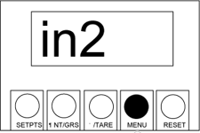
2. Once you've com- pleted all steps, the unit displays:
(example on right) |
|
|
|
| To
begin operation: Reinitialize the unit (press RESET twice
or press MENU until RST flashes on the display). When a numeric
reading appears, the unit is operational.
|
|
Determining
Reading Offsets
Meters scaled without known loads may reflect an offset in run mode. For
example, say you set RD1 to 0 and RD2 to 100, but when the minimum load
is applied, a value of û1.5 displays on the front panel.
To correct the reading offset:
1. With zero load applied, note the reading on the display.
2. Subtract that amount from the RD1 and RD2 values you originally
entered.
In the example, the offset would be û1.5. If RD1 is to read 0 in run mode,
it must be reentered as 1.5. RD2 must likewise be reentered as 101.5 if
the meter is to read 100 when the maximum load is applied.
3. Repeat the steps for "Scaling Without Known Loads," but when
the values for IN1 and IN2 display, do not change them. Instead, press
MENU to move to the prompts for RD1 and RD2 and make the necessary
changes.
4. Reinitialize the unit and resume operation.
|